ElectroSeed MMWB RB
40 in stock
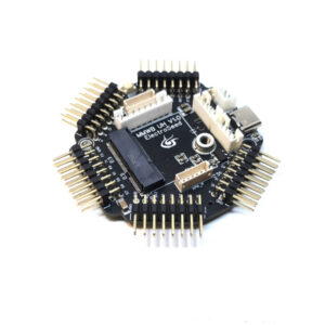
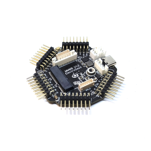
The MMWB RB (MicroMod Wheel Board Radio Boost) allows you to connect daughterboards in MicroMod format and offers unique features. Ideal for wireless, battery powered configurations, it proposes a Lithium-Ion charging circuit (3A Max), as well as a Boost circuit to deliver 5v to Nextion screens or lots of RGB leds.
16,98 € incl. VAT (14,15 € excl. VAT)
Le Bodac est un montage qui permet de mettre en oeuvre plusieurs boutons sur une seule entrée analogique, tout en ayant la possibilité de les avoir appuyés en même temps. Le montage est simple : une résistance entre chaque borne des boutons, et un seul fil entre chaque bouton.
Ce pack de résistances de précision 1%, permet de réaliser un Bodac pour 5 boutons ou moins.
En choisissant un package NodeBlue, vous bénéficiez de la configuration de votre choix. Un formulaire de configuration vous sera envoyé après votre commande afin de préciser la programmation souhaitée. Ce formulaire est similaire à cette page, qui permet de tester si la configuration est possible. La carte sera programmée et testée en conséquence, et les schémas de câblage vous seront fournis. Si vous ne prenez pas de package, vous devrez programmer la carte vous même avec l'IDE Arduino. Plus d'information sur les différences entre le package standard et le package pro sont disponibles sur cette page.
40 in stock
| Weight | 0,02 kg |
|---|---|
| Dimensions | 1 × 1 × 1 cm |
Description
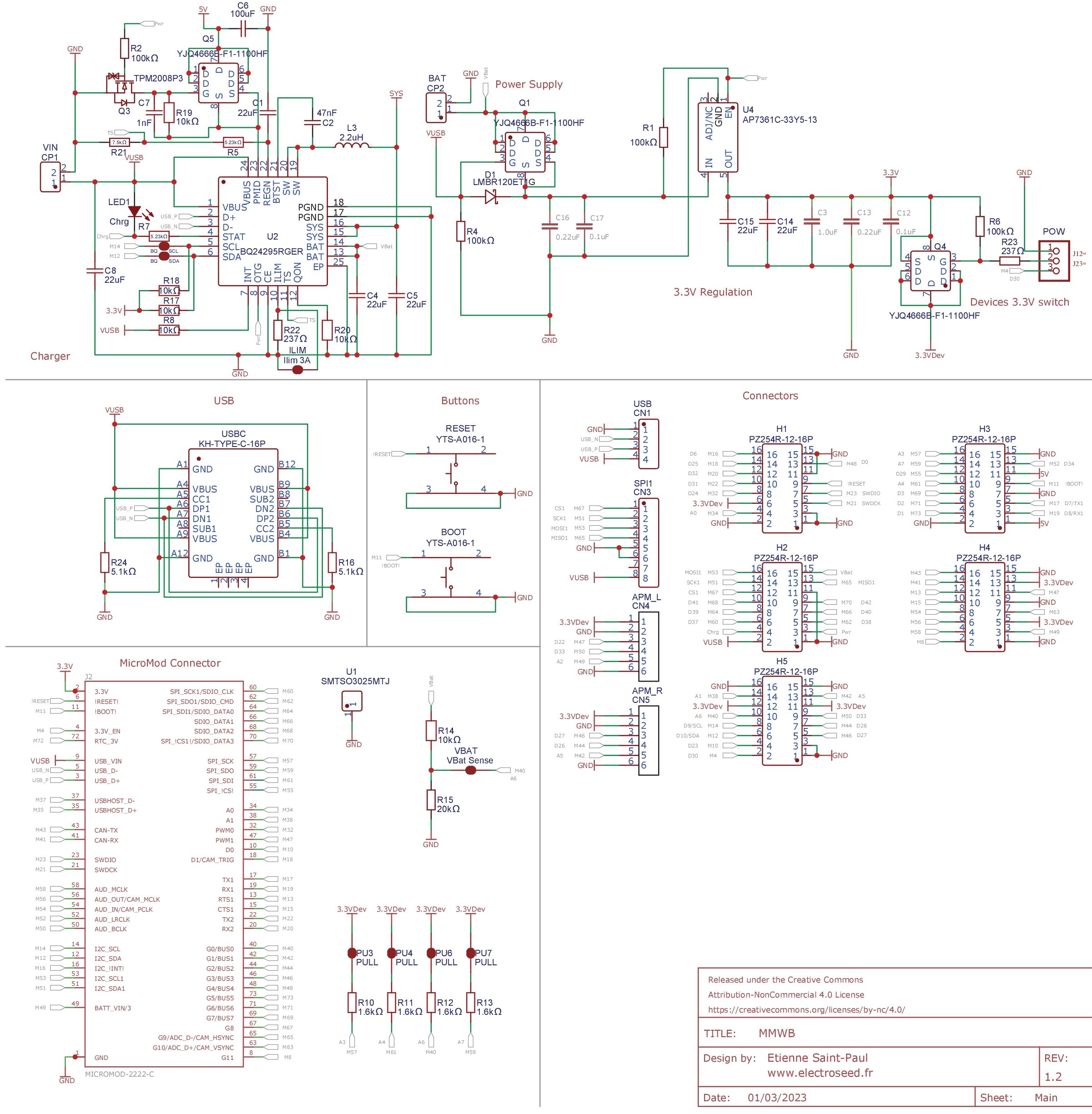
- LiPo battery management circuit, including a charging circuit and a 5v boost circuit, which can power a Nextion screen, 7-segment displays, RGB Leds or any other peripheral requiring a 5v power supply.
-
4 precision pull-up resistors on analog inputs to connect Bodacs, which allows you to put up to 20 buttons in addition to the other 39 remaining inputs.
-
A mosfet to switch the power supply to 3.3v peripherals, which reduces battery consumption when using potentiometers or other sensors.
- 8-pin JST 2.0 connector to connect natively to Fanatec bases (using our SRM Quick Release), and also to Thrustmaster bases (also possible by a 2×3 dupont connector).
- 2 x 6-pin JST 1.5 connectors for connecting 2 Fanatec APM paddles or any other system with up to 2 digital paddles and one analog paddle per port.
- A 5v power connector to connect to the Simagic or Moza bases (thanks to our Simagic and Moza Quick Releases), the NRF52840 daughter board allowing native radio communication with Simagic bases (inputs only, 32 functions).
- A 4-pin JST 2.0 connector to easily connect an aviation connector for steering wheels operating in USB or a panel mount USB connector for wireless wheels (for battery charging or for firmware updates).
- A USB-C connector to program the board or connect a USB extension.
You’ll find below a table with the different daughter boards to help you choose the one corresponding to your needs. All boards can work via USB or native connection with Fanatec or Thrustmaster bases. The management of Nextion screens, RGB LEDs and 7-segment displays is done using the SimHub software and needs a NRF Dongle to work wirelessly.
Schematics
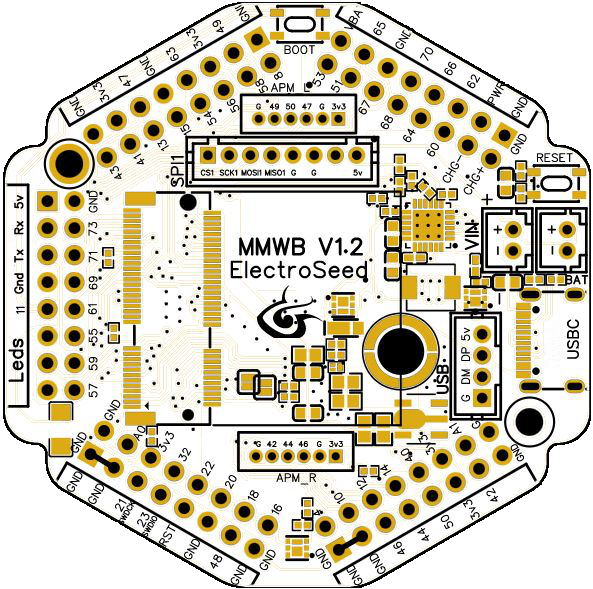
Pinout
Tutorials
- Calibration with the serial monitor
- Click on the “Cal” input of the analog input module, the sensor module (eg AS5600) or the “Range” module. The module name can be “Accel”, “X”, “Y” or “Z”, or something else depending on the application. Once cal is pressed, a message appears in the serial monitor window. Follow the instructions.
- Once the calibration is complete, double click on the module to change the low and high deadband parameters. Check in the controller tab that when the axis is completely released the value is 0 and when it is fully released the value is 65535. Adjust the dead zones if necessary. Click on “Invert” if you need the axis to work in an inverted way.
- Manual Calibration (if the USB Virtual serial port is not present or used by another non compatible module)
- Double-click on the analog input module “X”, “Y” or “Z” (or any other name depending on the project) concerned by the axis.
- Position the axis to the minimum, copy the value displayed in the controller tab (adding a small margin), in the “In Min” parameter of the module.
- Position the axis to the maximum, copy the value displayed in the controller tab (by removing a small margin), in the “In Max” parameter of the module.
- change the low and high deadband parameters. Check in the controller tab that when the axis is completely released the value is 0 and when it is fully released the value is 65535. Adjust the dead zones if necessary.
Once each axis has been done :
- Save the project so that the settings are saved, either by using the “Save project” menu or with the CTRL-S key combination. If the project is read-only, use the “Save As” menu and choose another name.
- Select the com port among those detected (disconnect any other detected boards to be sure to program the board you want).
- Upload the project to the board (“Upload” button).
The settings are saved in the flash memory of the board and are restored at each restart.
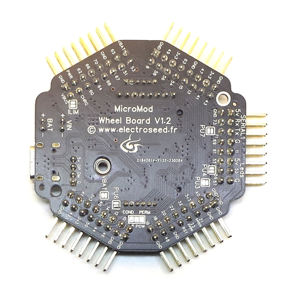
Dimensions
3D Model (.obj and .step Format) : https://www.electroseed.fr/docs/MMWB/MMWB_3DModel.zip
Related products
-
MicroMod
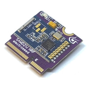
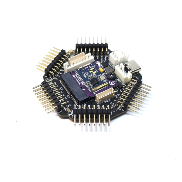
MicroMod SamD21J NRF
With a 32-bit ARM Cortex-M0 MCU, the ElectroSeed MicroMod SAMD21J NRF Processor Board provides a powerfull and versatile platform. With the NRF24L01 radio module and its ceramic antenna, make your wireless projecy easily with a maximum of inputs.
The ATSAMD21J18 used is a 32-bit ARM Cortex-M0, running at 48 MHz, has 256 KB of flash memory, 32 KB of SRAM, 6 SERCOM interfaces, and other features.
Number of inputs/outputs : 45 including 16 analog.
SKU: 677 -
-
Radio
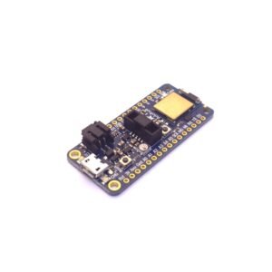
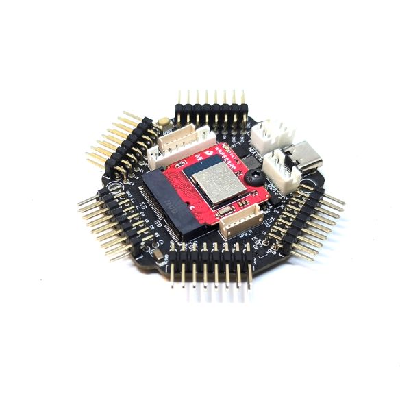
Adafruit NRF52840 Feather Express
This board enables connecting buttons, switches, encoders, potentiometers, rotary switches, joysticks and various sensors, to easily deploy wireless solutions.
An battery charging circuit allows you to power the board with a battery for embedded applications, along with an internal connexion in order to measure precisely the battery voltage, so you will know the charge that’s left.
SKU: 357 -
MicroMod
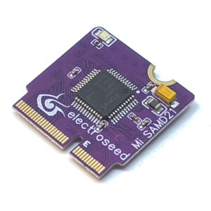
MicroMod SamD21
With a 32-bit ARM Cortex-M0 MCU, the ElectroSee MicroMod SAMD21 Processor Board provides you with an economical and easy to use development platform. With the M.2 MicroMod connector, connecting your SAMD21 Processor is a breeze. Simply match up the key on your processor's beveled edge connector to the key on the M.2 connector and secure it with a screw (included with all Carrier Boards).
The ATSAMD21G18 used is a 32-bit ARM Cortex-M0, running up to 48 MHz, has 256 KB of flash memory, 32 KB of SRAM, 6 SERCOM interfaces, and other features. This MicroMod SAMD21 comes flashed with the UF2 bootloader.
SKU: 649