

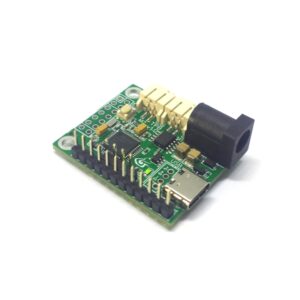
Carte QTPY_HX
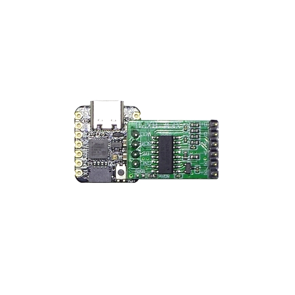
Pedals board QT_PY SamD21 + Hx711
This board enables connecting up to 3 load cells, buttons/encoders and various sensors, to easily build your own pedal set.
Several connectors give access to various peripherals.
Most Load Cell dedicated boards on the market use a potentiometer for sensitivity adjustment, which has many drawbacks: the potentiometer is usually located at the pedals level and is therefore difficult to adjust, moreover, they may tend to get disrupted regularly, especially on a dynamic simulator. On this PB_01 board, the measurment IC for the load cell is the Hx711, which proposes 3 different digital gains. Its 24-bit ADC makes it possible to have a high accuracy while exploiting the entire range of your sensor without needing this additional sensitivity adjustment potentiometer.
Node Blue Example for 1 Load Cell and 2 potentiometers : Hx711_2A_HID
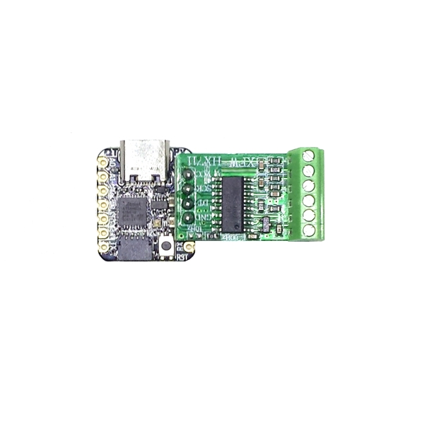
Along with the load cell, you will have access to 7 digital or analog inputs (12 bits), to connect for example additionnal potentiometers or angular hall effect sensors. The inputs are 3.3 V and are not 5 V tolerant.
From 4,00 €
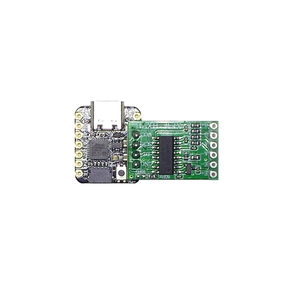
Pedals board QT_PY SamD21 + Hx711
This board enables connecting up to 3 load cells, buttons/encoders and various sensors, to easily build your own pedal set.
Several connectors give access to various peripherals.
Most Load Cell dedicated boards on the market use a potentiometer for sensitivity adjustment, which has many drawbacks: the potentiometer is usually located at the pedals level and is therefore difficult to adjust, moreover, they may tend to get disrupted regularly, especially on a dynamic simulator. On this PB_01 board, the measurment IC for the load cell is the Hx711, which proposes 3 different digital gains. Its 24-bit ADC makes it possible to have a high accuracy while exploiting the entire range of your sensor without needing this additional sensitivity adjustment potentiometer.
Node Blue Example for 1 Load Cell and 2 potentiometers : Hx711_2A_HID
Along with the load cell, you will have access to 7 digital or analog inputs (12 bits), to connect for example additionnal potentiometers or angular hall effect sensors. The inputs are 3.3 V and are not 5 V tolerant.
Tutorials
Wiring
nodeblue
file=examples/Boards/QTPySamD21/QTPYSamD21_Hx711_2A.txt
scale=0.75
type=wiring
interactive=false
Based on 0 reviews
Be the first to review “Carte QTPY_HX”
Related products
-
Pedals
Electroseed Tiny Pedals Board
Pedals board with vibration motor control
This board, based on the SamD21 micro-controller, makes it possible to interface buttons/encoders, various sensors, and a NRF24L01 radio module. Two I2C ports and an SPI port are accessible, for example to connect 2 AS5600 magnetic angle sensors or a contactless magnetic sensorThis board also offers a motor control circuit, allowing the control of up to 2 vibration motors to simulate ABS, TC, etc., if the game sends this information, and by interfacing with SimHub software. The motors can be powered by USB or by a separate power supply (voltage between 4 and 16 V). The maximum current is 500 mA per motor, for a total power of 1 W max. Motor speeds are controlled by high frequency PWM signals, so commutation signals are inaudible.You will have access to 17 I/O including 13 analog inputs (12 bits). The inputs are 3.3 V and are not 5 V tolerant. The SamD21 operates at 48 MHz.A NodeBlue package is included with the board, so you can have any configuration you need. A configuration form will be sent after your order, so you can specify the desired programming. The board will be programmed accordingly and the wiring schematics will be provided.SKU: 628
There are no reviews yet.