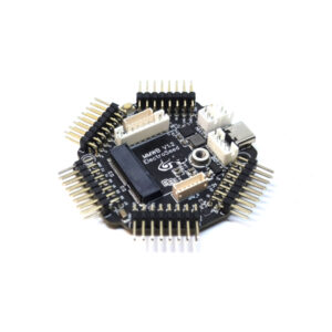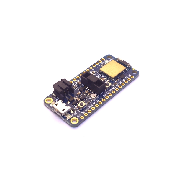
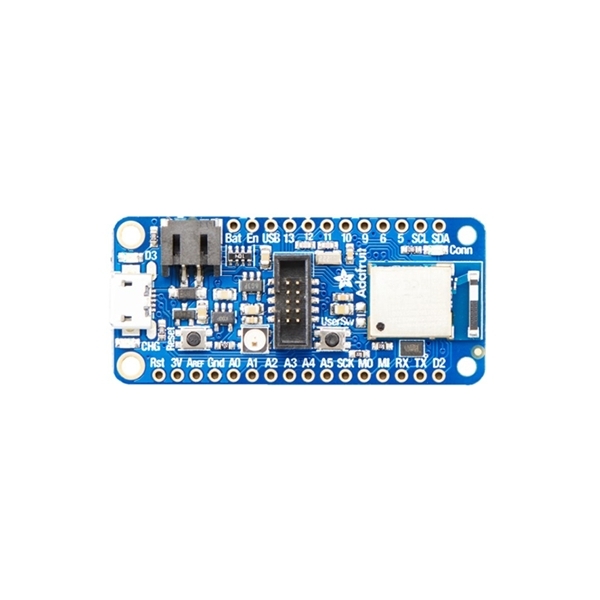
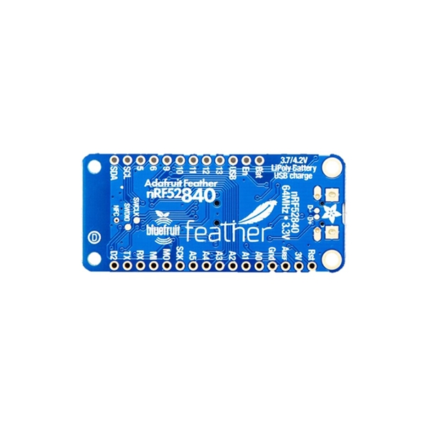
Adafruit NRF52840 Feather Express
100 in stock
This board enables connecting buttons, switches, encoders, potentiometers, rotary switches, joysticks and various sensors, to easily deploy wireless solutions.
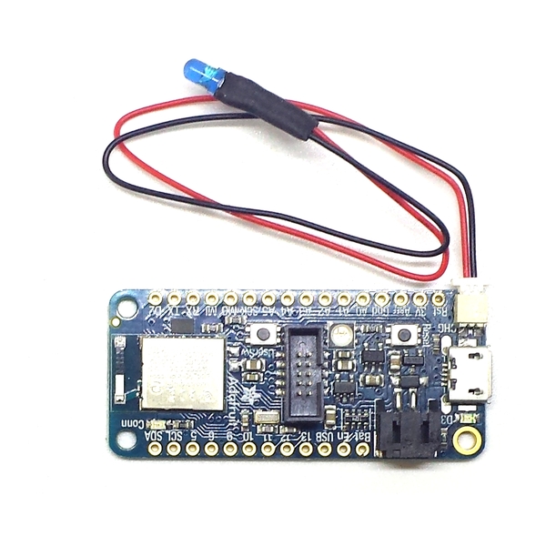
An battery charging circuit allows you to power the board with a battery for embedded applications, along with an internal connexion in order to measure precisely the battery voltage, so you will know the charge that’s left.
25,75 € incl. VAT (21,46 € excl. VAT)
Le Bodac est un montage qui permet de mettre en oeuvre plusieurs boutons sur une seule entrée analogique, tout en ayant la possibilité de les avoir appuyés en même temps. Le montage est simple : une résistance entre chaque borne des boutons, et un seul fil entre chaque bouton.
Ce pack de résistances de précision 1%, permet de réaliser un Bodac pour 5 boutons ou moins.
Les supports IO permettent d'éviter de souder directement sur la carte, évitant ainsi les courts-circuits. Vous pourrez connecter vos boutons/encodeurs/etc avec des câbles dupont. La carte sera fournie avec les supports déjà soudés.
En choisissant un package NodeBlue, vous bénéficiez de la configuration de votre choix. Un formulaire de configuration vous sera envoyé après votre commande afin de préciser la programmation souhaitée. Ce formulaire est similaire à cette page, qui permet de tester si la configuration est possible. La carte sera programmée et testée en conséquence, et les schémas de câblage vous seront fournis. Si vous ne prenez pas de package, vous devrez programmer la carte vous même avec l'IDE Arduino. Plus d'information sur les différences entre le package standard et le package pro sont disponibles sur cette page.
100 in stock
You will have access to 22 I/Os, including 7 analog inputs with a 12 bits ADC. One additional digital input is available for the on board user switch, as well as an “NFC” pad under the board if another input is needed. The inputs are 3.3 V and are not 5 V tolerant. The heart of this board is the NRF52840, the most suitable microcontroller on the market for embedded systems. Clocked at 64 MHz, it also offers 2 SPI ports, 1 I2C port , and 1 serial port. Like on all the boards we propose, we have enhanced the kernel in order to offer as much features as possible.
Note : If you need anything else than inputs (leds, Nextion screen, etc), you will have to use a NrfDongle dongle.
Drivers Download : Adafruit Drivers
| Weight | 0,02 kg |
|---|---|
| Dimensions | 1 × 1 × 1 cm |
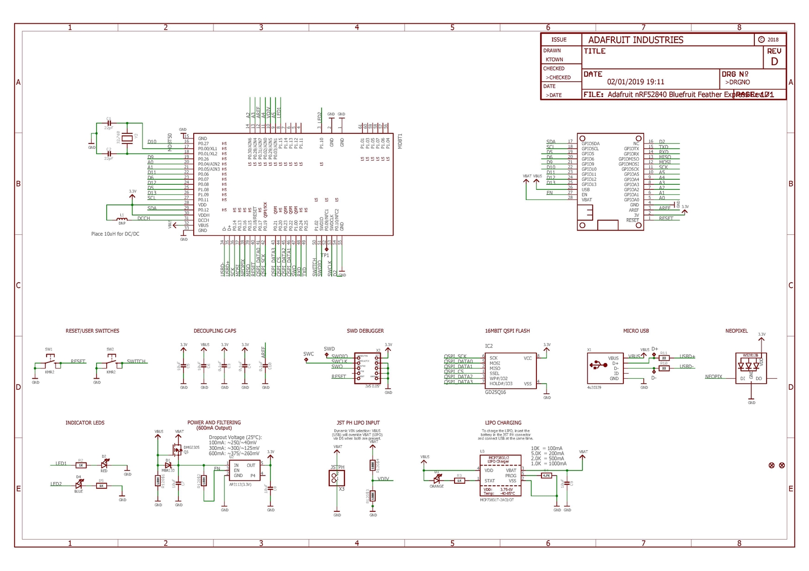
Schematics
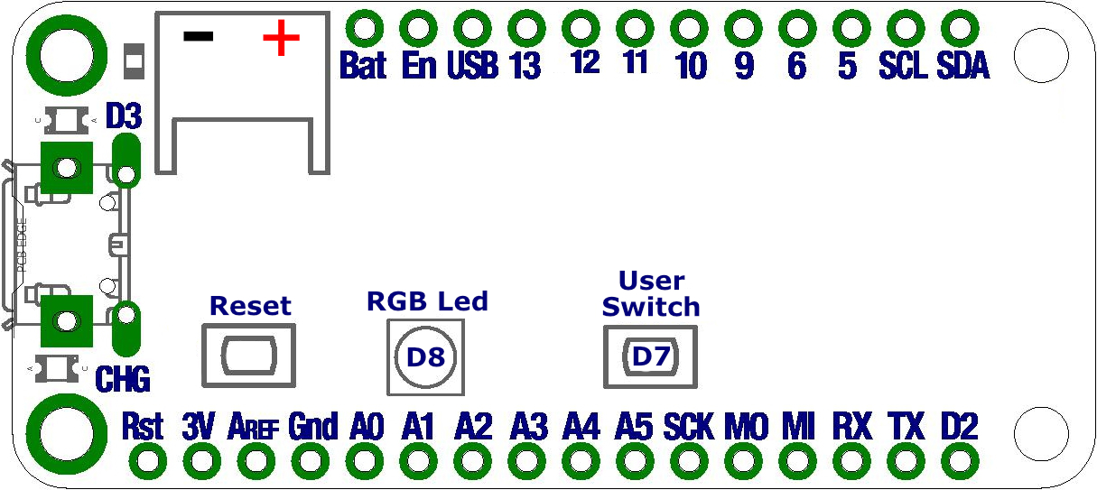
Pinout
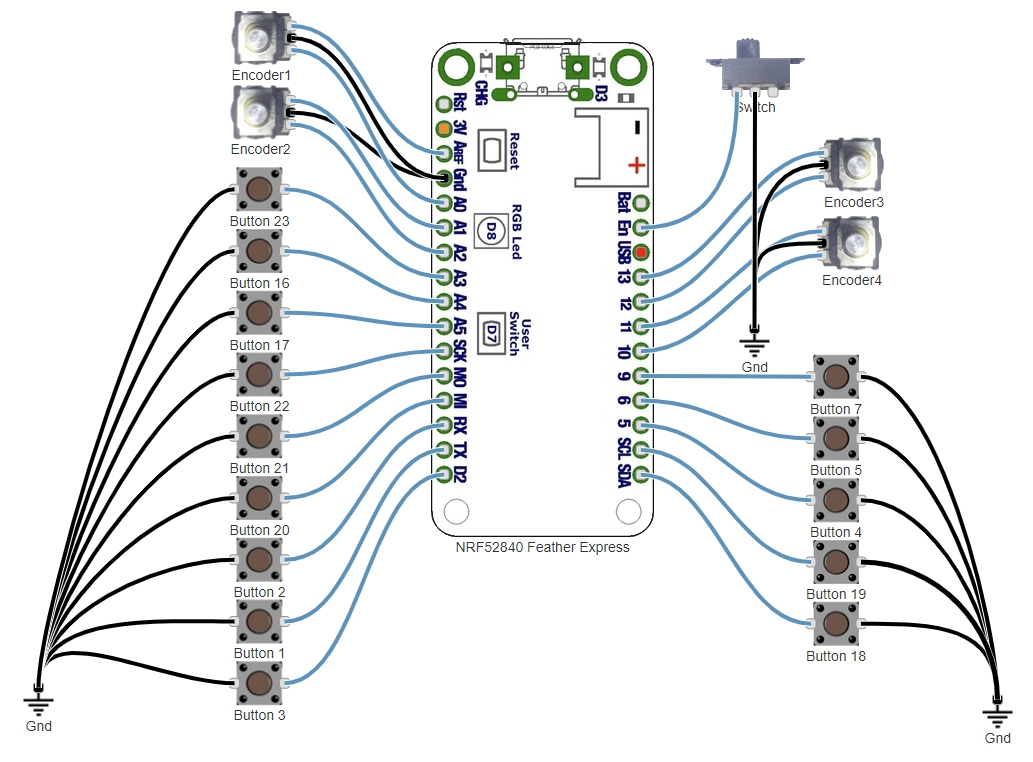
Default program :
Tutorials
- Calibration with the serial monitor
- Click on the “Cal” input of the analog input module, the sensor module (eg AS5600) or the “Range” module. The module name can be “Accel”, “X”, “Y” or “Z”, or something else depending on the application. Once cal is pressed, a message appears in the serial monitor window. Follow the instructions.
- Once the calibration is complete, double click on the module to change the low and high deadband parameters. Check in the controller tab that when the axis is completely released the value is 0 and when it is fully released the value is 65535. Adjust the dead zones if necessary. Click on “Invert” if you need the axis to work in an inverted way.
- Manual Calibration (if the USB Virtual serial port is not present or used by another non compatible module)
- Double-click on the analog input module “X”, “Y” or “Z” (or any other name depending on the project) concerned by the axis.
- Position the axis to the minimum, copy the value displayed in the controller tab (adding a small margin), in the “In Min” parameter of the module.
- Position the axis to the maximum, copy the value displayed in the controller tab (by removing a small margin), in the “In Max” parameter of the module.
- change the low and high deadband parameters. Check in the controller tab that when the axis is completely released the value is 0 and when it is fully released the value is 65535. Adjust the dead zones if necessary.
Once each axis has been done :
- Save the project so that the settings are saved, either by using the “Save project” menu or with the CTRL-S key combination. If the project is read-only, use the “Save As” menu and choose another name.
- Select the com port among those detected (disconnect any other detected boards to be sure to program the board you want).
- Upload the project to the board (“Upload” button).
The settings are saved in the flash memory of the board and are restored at each restart.
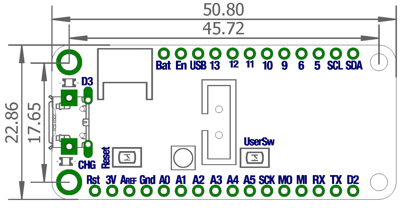
Dimensions
Related products
-
Radio, MicroMod
ElectroSeed MMWB RB
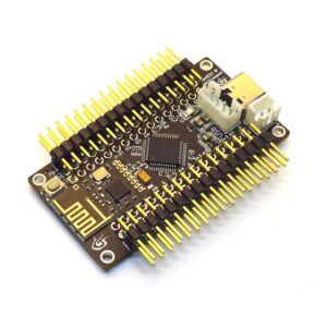
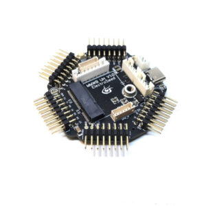
The MMWB RB (MicroMod Wheel Board Radio Boost) allows you to connect daughterboards in MicroMod format and offers unique features. Ideal for wireless, battery powered configurations, it proposes a Lithium-Ion charging circuit (3A Max), as well as a Boost circuit to deliver 5v to Nextion screens or lots of RGB leds.
SKU: 607 -
-
-
Radio
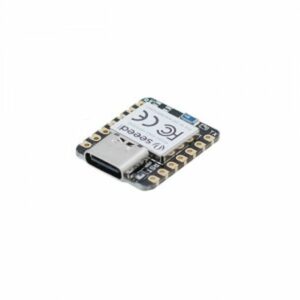
Seeed Studio XIAO BLE
The Seeeduino XIAO BLE board brings you the power of a nRF52840 in one of the smallest form factor, and allows to deploy wireless projects at a small cost. It includes a Texas Instrument BQ24101 battery charging circuit, and the battery charge level can be measured.
Thanks to Node Blue, this board enables connecting buttons, switches, encoders, potentiometers, rotary switches, joysticks and various sensors.
SKU: 613