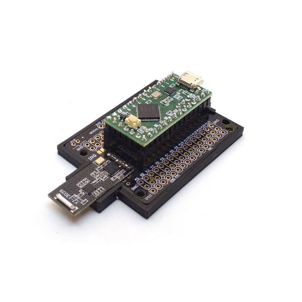
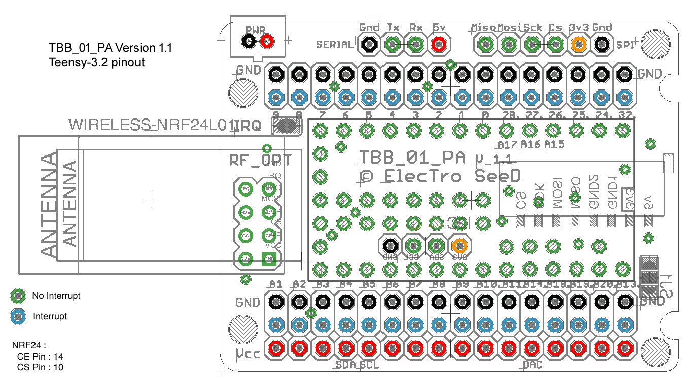
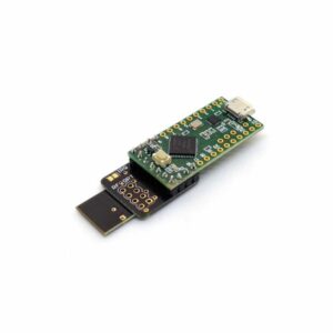
Breakout board for Teensy-LC and Teensy-3.2 (assembled)
This board enables connecting buttons/encoders and various sensors, and an amplified radio module with a micro ceramic antenna.
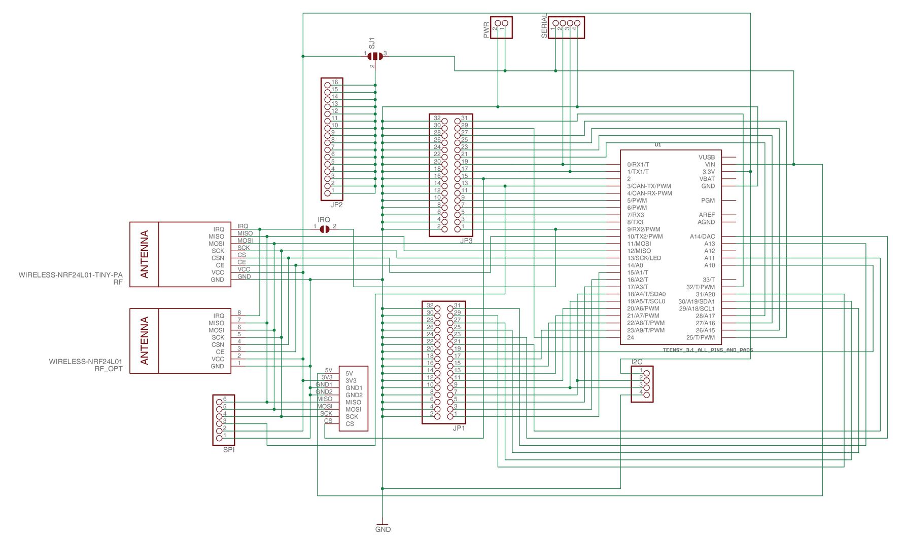
Several connectors give access to various peripherals.
– With a Teensy LC, you will have access to 27 I/Os (22 when using a radio module), including 12 analog inputs (16 bits), and a amplified output on the pin 17 to drive Neopixel LEDs for example. The inputs are 3.3 V and are not 5 V tolerant. The Teensy LC operates at 48 MHz max.
– With a Teensy 3.2, you will have access to 37 I/Os (32 when using radio), including 19 analog inputs (16 bits) and 32 digital inputs. All digital pins are tolerant to 5 V. Teensy 3.2 operates at 72 MHz max but can be overclocked at 120 Mhz.
Description
Connectors :
- Radio modules
- SPI Port
- 8 pins JST to connect the board to Fanatec bases
- I2C Port
- Asynchronous Serial Port
This board can be powered by Teensy's micro-USB or with a cable directly soldered to the board.
This board can be mounted in the Quick Release from ThomConcept or on any button plate.
A printed PLA support is included.
This board can be powered by Teensy's micro-USB or a JST 2.0mm connector, or with a cable directly soldered to the board.
This board can be mounted in the Quick Release from ThomConcept or on any button plate.
A printed PLA support is included.
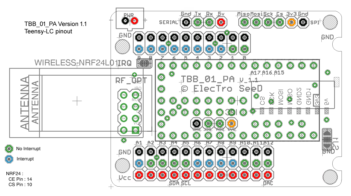
Teensy LC :
The Teensy LC operates at 48 MHz max. All inputs are 3.3V only and are not 5V tolerant. All outputs are 3.3V except D17 pin which is 5V. You will have access to 27 I/Os (22 when using a radio module).
- 22 Digital Inputs / Outputs : D0, D1, D2, D3, D4, D5, D6, D7, D8, D9, D15(A1), D16(A2), D17(A3), D18(A4), D19(A5), D20(A6), D21(A7), D22(A8), D23(A9), D24(A10), D25(A11), D26(A12)
- 5 Digital Inputs / Outputs dedicated to SPI or radio module : D10 (CS), D11(MOSI), D12(MISO, D13(SCK)
- 12 Analog Inputs multiplexed on a 16 bits ADC : A1, A2, A3, A4, A5, A6, A7, A8, A9, A10, A11, A12
- 1 Digital output amplified to 5V to drive RGB Leds
- 1 Analog Output on a 12 bits DAC : A12
- With the battery charging circuit, the A7 pin is used to measure the battery voltage, in order to evaluate the autonomy left.
Teensy 3.2 :
Teensy 3.2 operates at 72 MHz max but can be overclocked at 120 Mhz. All digital pins are tolerant to 5V, but analog inputs must stay under 3.3V. All outputs are 3.3V. You will have access to 37 I/Os (32 when using a radio module). Some pins are analog only (A10, A11, A12, A13 and A14).
- 29 Digital Inputs / Outputs : D0, D1, D2, D3, D4, D5, D6, D7, D8, D9, D15(A1), D16(A2), D17(A3), D18(A4), D19(A5), D20(A6), D21(A7), D22(A8), D23(A9), D24, D25, D26(A15), D27(A16), D28(A17), D28(A18), D29(A19), D30(A20), D31(A21), D32
- 5 Digital Inputs / Outputs dedicated to SPI or radio module : D10 (CS), D11(MOSI), D12(MISO, D13(SCK)
- 12 Analog Inputs multiplexed on a 16 bits ADC : A1, A2, A3, A4, A5, A6, A7, A8, A9, A10, A11, A13, A14, A15, A16, A17, A18, A19, A20
- 1 Analog Output on a 12 bits DAC : A14
- With the battery charging circuit, the A12 pin is used to measure the battery voltage, in order to evaluate the autonomy left.
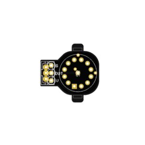 CI_DIGIPOT_6_Grayhill
1 × 1,50 €
CI_DIGIPOT_6_Grayhill
1 × 1,50 €  BoardServer
1 × 0,00 €
BoardServer
1 × 0,00 € 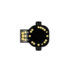 CI_DIGIPOT_12_Mini
1 × 1,50 €
CI_DIGIPOT_12_Mini
1 × 1,50 € 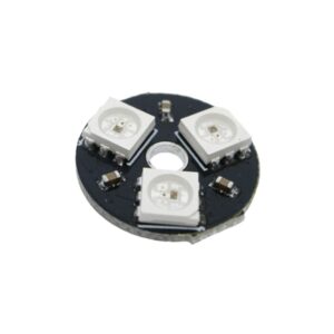 Triple RGB Led WS2812B
1 × 1,40 €
Triple RGB Led WS2812B
1 × 1,40 € 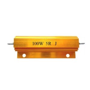 Power resistor 5 Ω 100 W
1 × 4,50 €
Power resistor 5 Ω 100 W
1 × 4,50 € 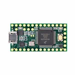 Teensy 3.2
1 × 25,75 €
Teensy 3.2
1 × 25,75 € 


There are no reviews yet.